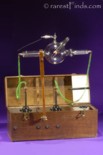
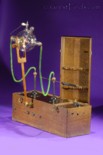
Early and rare portable X-ray machine. Sold!
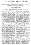
Issued patents this machine and X-ray tube are based on, click on any image to see larger image!

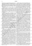
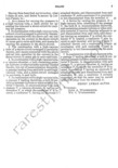


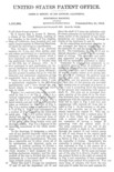
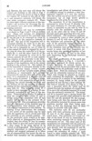
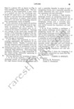

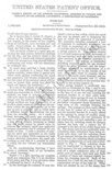
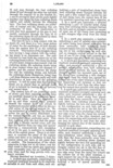


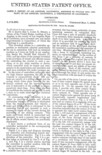
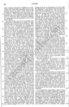
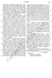
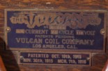
This portable X-ray outfit was manufactured by a little company first doing business under the name SEELEY ELECTRICAL LABORATORY, and, PATENTS PENDING (two machines are known with this name, serial numbers 130, and G108); later VULCAN COIL COMPANY, and still with the remark, PATENTS PENDING, however, on a separate brass tag which includes the remark, PATENTED OCT. 19th, 1915 NOV. 30th 1915 MCH.[sic] 7th, 1916 (one machine known with this name, the one offered here with serial number G209); and, after yet another name change, VULCAN ELECTRIC COMPANY, LOS ANGELES, CAL. and at this time with the remark, PATENTED (one machine known, serial number not known).
All three companies were located in LOS ANGELES, CAL. U.S.A. The Vulcan Coil Co., was located at 239 South Los Angeles Street, Los Angeles, Cal., according to a trade catalogue called
“BULLETIN L,” and issued by the The Vulcan Coil Co., (every word typed in bold/italic is an active link on this webpage!)
Only very few of these machines were sold; the one offered here has serial number G209, see picture #9.
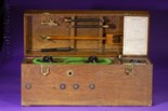
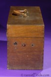
The machine is housed in a dove-tailed golden-oak case measuring 24.75 by 8.75 by 11 inches and weighing a hefty 57 lbs!
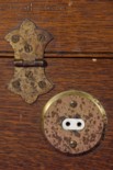
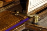
The wood panels are 0.375 or ⅜ inches thick and are not strong enough for the weight of the machine. Also, the lid has a provision to hold the lid in place while the machine is being used by a brass lever, see picture #13. The leverage of the weight of the lid so close to the hinges is more proof that the engineers designing this machine may understood electricity, they certainly did not understand mechanics.
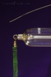
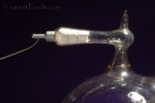
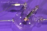
The tube is a cold cathode ion-X-ray tube with autoregeneration made by Kesselring.
The anode and cathode are connected to the brass-balls energized by the high-tension on top of the columns as shown in the pictures.
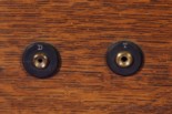
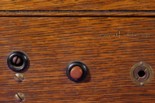
The two terminals on the left in the front marked “D”, see picture #6 and 8, are to connect electrodes for “Diathermy or Thermo-Penetration” treatment; the two terminals on the right have a larger diameter and are marked “T” and “X” for “Tesla Currents” and “Ouidin Affluve” for which this machine provides separate windings according to the “BULLETIN L”. In short, this machine is “covering the entire treatment range;” for instance, besides taking X-rays, this machine purports to treat and heal, Diabetes, Gonorrhoea [sic], Hemorrhoids, Impotence, Vaginitis, and many more!
In the back of the machine is a female connector for the 110 Volt AC supply, see picture #10. On the right side is the selector switch for the strength of the current, see picture #11. The switch is either turned with a screwdriver or the knob maybe missing. In the center is the red knob to activate the machine. The purpose of the plug to the right of the red knob is not known to me.
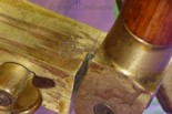
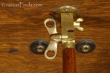
The front also has the provision to attach the wooden X-ray tube holder. The large wing-nut determines the angle of the holder; the smaller wing-nut blocks the brass fitting from turning sideways by forcing a conical pin into the bushing to increase its diameter, hence blocking it from turning, see picture #14.
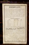
The paper-label inside the lid provides an “EXPOSURE-SCHEDULE” for different parts of the human body to be X-rayed.
Condition:
I did not power-up this machine, I can therefore not claim that it works. It seems to be complete besides the knob on the right hand side of the machine which maybe missing. The X-ray tube is perfect without any signs of use, or defects.
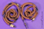
Picture #19 shows the original insulated wires to connect the X-ray tube. The rubber insulation is hardened and bridle. I un-soldered the connectors and made new wires with silk insulated stock from the period.
History:
X_Ray: Wilhelm Conrad Röntgen (March 27, 1845 — February 10, 1923) was a German mechanical engineer and physicist, who, on November 8, 1895, produced and detected electromagnetic radiation in a wavelength range known as X-rays or Röntgen-rays, an achievement that earned him the inaugural Nobel Prize in Physics in 1901, the year the Nobel Prize in Physics was awarded the first time.
For ethical reasons, Röntgen did not seek patents for his discoveries, holding the view that it should be publicly available without charge. For this reason, Röntgen’s discovery proved to be a prolific one.
Several manufacturers of medical apparatus became active in the field and built X-ray machines. This was during the time of the industrial age on the Eastern Seaboard. Railroads were expanding, workers were unloading ships on the docks, and lots of people were breaking their bones and being taken to the hospital if there was one nearby. Early X-ray machines were not portable and it caused a problem as most people who broke their bones weren’t near hospitals.
Cathode ray tubes were easy to make and use. Anybody who had a little bit of money could make themselves a cathode ray tube, buy a Rhumkorff coil, and take pictures. One of the most interesting aspects of the history is how X-rays became medical. They weren’t always medical. Early in the 20th century lay entrepreneurs would set up stands to take X-rays in public places, like hot-dog stands we would find today. People would set up stands on the street near a source for power. By-passers had their X-ray pictures taken to give to their beloved as if it were the most beautiful picture they had ever had.
In the novel Magic Mountain, by Thomas Mann, protagonist Hans Castorp holds up his beloved’s X-ray image of her chest and says “How often did I hold it, how often pressed it to my lips.” Many people (outside of the novel) who bought X-rays didn’t buy a medical X-ray; it wasn’t being taken by physicians. Instead, it was being taken by photographers.
One of the interesting changes is how the field of taking an X-ray picture becomes medical. That change is associated with the claim that the radiologist is not a photographer, taking the picture for the patient to take home or give to someone else. Rather, the radiologist claims that they are a consultant. When making this claim, some use the specific example of physicians who do a blood count. If you come to me as a hematologist and I do a blood count, they say, I am not going to give you the smear. In a similar way, what you are buying from me as a radiologist is my expert opinion about what the X-ray shows, not the actual physical image itself. In this way the X-ray worked its way into the medical world.
Vulcan Coil Co: Electricity in hospitals (and elsewhere) was still new. People were still trying to work out whether to use DC or AC current, and were still trying to agree on the voltage to use.
Edison who propagated Direct Current (DC), and Tesla who saw Alternating Current (AC), as the only way to power the energy grid of the future were still at war against each other. At the height of the Current War, the Chicago World’s Fair, also known as World’s Columbian Exposition took place in 1893. General Electric bid of $554,000 to electrify the fair using Edison’s direct current system lost to George Westinghouse, who said he could power the fair for only $399,000 using Tesla’s alternating current system.
There was a lot of unprotected electricity, loose un-insulated wires switches and more, and patients and occasionally physicians would get electrocuted in hospitals. The Vulcan Coil offered here has a female power plug, see picture #10. The power cord therefor had two male pins carrying 110 Volts once the power cord was carrying power! They obviously had not figured out that connectors carrying the power needed to be female, whether they where on a unit to be powered or on the power cord to carry the power to the machine to be powered. I have seen several other devices or machines where live powered contacts where exposed to the operator! Even the X-ray tube on this machine has exposed terminals to carry the high voltage.
I found the following entry in the Los Angeles Herald, Volume XLI, Number 54, 2 January 1915: “Over Hundred Factories Added Within Past Year.”
One of the factories added in 1914 was “Vulcan Coil company. X-ray and electrical apparatus.”
The entry was probably triggered by the change of the the Company name from SEELEY ELECTRICAL LABORATORY to VULCAN COIL COMPANY, which would date the machine offered here to 1915 as the company name changed again shortly after to VULCAN ELECTRIC COMPANY.
James E. Seeley is definitely the individual who is the brain behind the machine offered here and the holder of many patents; his earliest application dates to February 8, 1901, for an ARTIFICIAL LIMB. He filed his application as assignor to W.W. SWEENEY CO., LOS ANGELES.
While he was still waiting to have his first application granted, he applied for a second patent on August 2, 1901, for STRONG LIGHT BODY AND METHOD OF PRODUCING SAME, relating to artificial limbs. At the time he was still an assignor to W.W. SWEENEY CO.
His first application for an ARTIFICIAL LIMB was granted on February 4, 1902 and the patent no. 692,719 issued.
His second application for the STRONG LIGHT BODY AND METHOD OF PRODUCING SAME, was granted on August 5, 1902, and the patent no. 706,498 issued.
Seeley and Sweeney therefore knew each other as early as February 8, 1901, when Seeley applied for his first patent.
Seeley was not the only assignor to W.W. SWEENEY CO.; an individual with name Leo Stumpf as assignor to W.W. Sweeney Co., was issued the patent number 692,803 on February 4, 1902, for STUMP-SOCKET FOR ARTIFICIAL LIMBS.
By July 14, 1904, Sweeney seems to have changed the name of his company to, THE SWEENEY SURGICAL MANUFACTURING CO., LOS ANGELES. Seeley applied on this day as assignor to Sweeney’s new company yet another patent for METHOD OF PRODUCING BODIES. The patent was granted on July 25, 1905, and the no. 795,734 assigned.
By February 9, 1905, William W. Sweeney seemed to be working for, THE PACIFIC SURGICAL MANUFACTURING Co., as he is named as assignor for this company in his application for a patent for a JOINT. Part of the patent claim reads as follows: “The class of furniture it is especially applicable is that where the attached parts are metallic — for example, in operating-tables used in hospital services.” Sweeney received patent no. 823,451 on June 12, 1906 for his JOINT invention. He received another patent for a PORTABLE STERILIZING APPARATUS, on March 13, 1906, number 815,313 still as assignor to THE PACIFIC SURGICAL MANUFACTURING CO.
Seeley’s earliest patent relating to X-ray was issued on October 24, 1905, number 802,413 with the title, ELECTRICAL APPARATUS. “This invention relates, primarily to an apparatus for producing electrical discharges of high frequency and intensity. Such discharges are used for the production of X-ray effects and in various therapeutical and other applications.” Seeley was yet the assignor to another company in Los Angeles, the SYCHRONOUS STATIC CO., LOS ANGELES. Seeley filed his application to this patent on July 20, 1904.
Seeley was granted other patents as assignor to SYNCHRONOUS STATIC CO. until February 25, 1908.
James E. Seeley thereafter seemed to have gone into another direction. He was involved into spark coils for internal combustion engines as early as July 12, 1905, when he applied for a patent under the title, “SPARKING DEVICE FOR GAS-ENGINES AND THE LIKE.” His application was granted nine years later on February 10, 1914 and the patent with the number 1,086,565, issued. He also received a patent for a SPARK-PLUG FOR INTERNAL-COMBUSTION ENGINES, patent number 978,494.
Interestingly, at the time he applied for these two patents, he was an assignor to THE HIGH FREQUENCY IGNITION COIL COMPANY, OF LOS ANGELES, CALIFORNIA. He was assignor to HIGH FREQUENCY IGNITION COIL CO., till February 10, 1914.
While still assigning patents to HIGH FREQUENCY IGNITION COIL CO., Seeley and Sweeney were among seven incorporators to incorporate THE SEELEY ELECTRICAL LABORATORY as reported in The Journal of Electricity, Power and Gas, Vol. XXVIII-No.22, published on June 1, 1912. The other five incorporators were, O.E. Campbell, W.D. Wikum, M.T. Terry, C.H. Bradley, J.P. Stockdale. The capital stock was $30,000.
This company only lasted less than two years, or until the VULCAN COIL CO., LOS ANGELES was founded in 1914.
Seeley applied for his first patent to protect the machine offered here with the title, ELECTRICAL MACHINE, on January 27, 1913. The patent is comprehensive and was granted on October 19, 1915, and patent no. 1,157,592 issued, see patent images above. Seeley was assigner to himself. The machine offered here was therefore manufactured before or around October 19, 1915, as the brass name tag still had the remark, “PATENTS PENDING.&Rdquo;
Seeley subsequently was granted another four patents as assignor to Vulcan Coil Co., of which two are the other patents to protect the machine offered here, patent no. 1,162,659, with title SPARK—GAP, issued November 30, 1915; and patent 1,174.293, with title CONTROLLER, issued March 7, 1916, see patent images above.
Patent papers reveal and provide interesting connections and insight.
There is little known about the Vulcan Coil Company, the company named on the brass tag of the machine offered here. An Advertisement published in
[2], page 14 (Advertisements have page numbers starting with page 1 past the general Index on page 748, also showing ads about other early floor model X-ray machines on pages 3, 9, and 11) give an address of 241 South Los Angeles St., Los Angeles, California. As mentioned above, in the
“BULLETIN L,” the address is 239 South Los Angeles Street, Los Angeles.
The one offered here is probably a machine built after the one with the serial number G108 but before the one with the unknown serial number as the patent dates were known and listed on a separate brass tag but the company brass tag still had the remark PATENTS PENDING.
 Most of the early X-ray tubes were powered by Rhumkorff induction coils powered by DC. An induction coil or “spark coil” after Heinrich Ruhmkorff is a type of electrical transformer used to produce high-voltage pulses from a low-voltage DC supply.
To create the flux changes necessary to induce voltage in the secondary coil, the direct current in the primary coil is repeatedly interrupted by a vibrating mechanical contact called an interrupter.
The Vulcan Coil offered here works on 110 Volt AC. The Vulcan Coil does not have the usual primary and secondary Coil. The Vulcan Coil is sort of a serial transformer whereby the primary and secondary coils are in series. This setup is also know as auto-transformer. A description of the Vulcan Coil was published in
[1], page 179-192. See also patent descriptions above.
This machine has seven variations in current strength which can be changed with the switch on the right hand side of the case. The current can be changed from 1 to 14 amperes roughly.
A portable machine like the one offered here could examine a patient at the scene of the accident if there was 110 Volt AC available nearby. However, the portable Vulcan Coil case weighs 57 lb and the physician taking the X-ray picture needed a strong back.
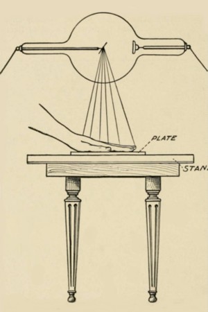
A basic setup to take an X-ray is shown in the picture on the left.
Vulcan Coil Co., was not the only manufacturing Co., making portable X-ray machines. The
electrotherapymuseum.com website features a collection of 11 such machines. The following portable machines are included in the collection of the museum, click on the brand-name to see the machine;
Frank S. Betz Co.;
Campbell mod. D;
The Rose, Empire Electric Co.;
Central Scientific Co., H.G. Fisher & Co.;
E.B. Meyrowitz;
Alastair ’s McIntosh;
The WM. Meyer Co.;
Laboratorio Electrico Sanchez;
Scheidel - Western X-Ray-Coil-Co.;
Victor Electric Co.; and
Vulcan Electric Company.
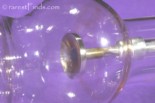
The X-Ray tube: The first-generation cold cathode or Crookes X-ray tubes were used until the 1920s. These tubes work by ionisation of residual gas within the tube. The positive ions bombard the cathode of the tube to release electrons, which are accelerated toward the anode and produce X-rays when they strike the target shown in picture #16. These tubes are also called ion-X-ray tubes.
Later on X-ray tubes had a heated cathode which emitted electrons by heating up atoms on the surface of the cathode.
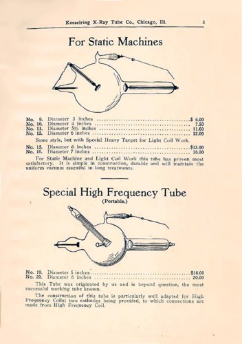
These early cold cathode tubes were manufactured between 1905 - 1920, and were used for diagnostic and therapeutic purposes. The anode is at the bottom, the cathode at the top, and the anticathode is just above the target.
The Vulcan Coil offered here is equipped with such a cold-cathode-ion tube manufactured by The Kesselring X-ray Tube Co. Chicago, IL. The picture on the right shows at the bottom the “Special High Frequency Tube (Portable)“ which was sold in two different sizes, with a diameter of 5 inches for $18.00, and with a diameter of 6 inches for $20.00. The tube included with the machine offered here is the larger one with the diameter of 6 inches, click on picture to download larger picture.
Founded by Hermann M Kesselring, the Kesselring X-ray Tube Company was a small manufacturer located at 136 and/or 652 W. Lake Street and 204 N Desplaines Street in Chicago. It operated at least until 1921.
A description of the Kesselring X-ray tube is on the
ORAU Museum of Radioation and Radioactivity website.
Crookes X-ray tubes were unreliable. As time passed, the residual gases forming the needed gas-pressure (air) to function properly would be absorbed by the cold cathode, reducing the pressure. When this happens, the resistance in the tube goes up and the voltage across the cathode and regeneration electrode builds up generating ‘harder’ X-rays, until eventually the tube stopped working. To prevent this, the gas-pressure needed to be regulated.
To achieve this, Henry Lyman of Philadelphia invented and patented his idea of Autoregeneration. The US patent with the number 1,092,489, was granted and issued on April 7, 1914, see patent images above.
Lyman devised a separate additional electrode he called “Regeneration Electrode” which he added in a separate chamber to his X-ray tube. This chamber “is filled with potassic hydrate or similar material” which is capable of giving off gas on heating. In the X-ray tube powered by the Vulcan Coil offered here the material is asbestos.
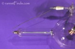
This separate chamber with the asbestos is located on top of the tube as shown in picture #15. The Regeneration Electrode is connected externally with a wire towards the cathode. The distance to the cathode would need to be adjusted for proper operation.
If the internal resistance was getting to high, the external applied voltage was reaching a value that created a spark between the wire connected to the Regeneration Electrode and cathode. The current flowing through the regeneration electrode heated the asbestos causing it to release trapped gases into the vacuum of the tube, hence, reducing the internal resistance.
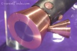
The copper cone used to shape the electrical field and thus guide the discharge between the anode and cathode, hence the lack of an electrical connection to the anticathode. “The cathode stream [from the ‘anode’ to the anticathode during the inverse discharge is focused into the cone attached to the anode, where it is destroyed without doing any damage to the tube.”
Inverse currents were undesirable for two reasons. First, they might cause the target to deteriorate, something that would shorten the life of the tube. Second, since the current through the tube would flow in two different directions, the X-rays would be coming from multiple points, e.g., the front and back of the target. The result: blurry radiographic images.
Picture #16 shows the anode with the platinum target and the “heavy anode” - with the large copper heat-sink surrounding the platinum anode. Picture #16 also shows the perfect platinum target surface where the beam strikes which does not show the slightest “crater” that over time is formed during operation, proof that this tube was hardly used if at all.
A further indication of the perfect condition of the tube is the clarity of the glass envelope. Over time, tungsten will be deposited from the target onto the interior surface of the glass envelope. This will slowly darken the tube and was thought to degrade the quality of the X-ray beam.
Vaporized tungsten condenses on the inside of the envelope over the “window” and thus acts as an additional filter and decreases the tube’s ability to radiate heat. Eventually, the tungsten deposit may become sufficiently conductive that at high enough voltages, arcing occurs. The arc will jump from the cathode to the tungsten deposit, and then to the anode. This arcing causes an effect called “crazing” on the interior glass of the X-ray window. As time goes on, the tube becomes unstable even at lower voltages and must be replaced. At this point, the tube assembly (also called the “tube head”) was removed from the X-ray system, and replaced with a new tube assembly. The old tube assembly was shipped to a company that reloaded it with a new X-ray tube.
Literature:
(Click on any title to see the online version of the book or publication if there is one.)
[2]
The International Journal of Orthodontia, Volume II, January - December, 1916.
Inventory Number 09349;
Price: Sold!
